I want to make a solar powered battery charger. I want to buy small solar panels 6x6in maybe, and wire them in series and parallel until I get the voltage and power I need. That part is easy.
What I don't understand is, how do you get a solar panel to output a "voltage". I've been reading and it seems like the voltage and amperage vary based on what kind of load is hooked up. So, if you want to keep your solar panel working at maximum efficiency, do you just design the circuit you're using to use the correct amount of current to keep the voltage of the panel at it's "peak" operating spec?
Take a look at this graph (which I stol... borrowed from http://www.reuk.co.uk/Measuring-the-Power-of-A-Solar-Panel.htm
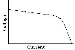
This is how normal PV solar panels look. At the midpoint of the curve is the panel's peak power output. So, I don't know how we'd control the voltage of the panel, but I know we can control the amount of current we're drawing from it. (Yes I know you can control the voltage AFTER it comes out of the panel, that's easy, voltage regulators are a dime a dozen.)
So, let's say my panel array's peak power output occurred at 15V at 1 amp. I'd have to deign a circuit to draw 1 amp to keep the panel at 15V, cause if it drew more than one amp, the voltage of the panel would be lower than 15V and if I drew LESS amperage, the voltage would be higher. Either way, the panel would be out of it's peak power output spot, correct?
Ok, so my project actually consists of two parts. I want to make a solar panel array to charge a car battery, which in turn will power my sophisticated NiMH and NiCd / LiPo charger that runs off of 12V. The car battery to sophisticated charger is easy, just hook it up.
So here is my initial brainstorm...
I need to make a panel array have a peak power output at 15ish volts and X amps. I put an X because I'm not sure if I want to build a simple trickle charger (probably around 500ma to 1A), or an actual charger, that'll switch to a trickle charger after the battery has reached 14V. Hmmm, actually I don't know if i will be able to have an actual charger, cause it'll take my panels our of peak power... unless I had two sets of panels, and both sets were used for fast charging and only one set was used for trickle...
Ok, now I need to know how to start charging the battery when the panel has enough power to produce 15V at whatever amperage I need. How would I do that? I'm completely dumbfounded here. This is really the only part I have no idea about... I don't know how to limit current. I mean yes, resistors are current limiting devices, but they limit current by simply using it, and making it into heat. Right? If I could limit the current I could have a relay that switched over at 14V to open my circuit... There's got to be a better way... EDIT: OR I could use a resistor to put a load on the panel, then measure the voltage with... something (I'd use a microcontroller, but that's way overkill). Then if the voltage was high enough, that something would let the circuit energize... I suck at electronics... haha
Next, the leads of the panels will go to a 14v voltage regulator (switching, as to not waste any energy). That "energy" if you will, will then be regulated by a few caps to smooth out the waveform and get rid of noise. This smooth, nice 14VDC power will be used to charge my battery by whatever charging circuit I want. As long as the entire cicuit pulls whatever amperage I need to keep my panel array near peak power output... I'm SURE I can find one online. I'll wire in diodes too so that the battery doesn't discharge at night or when it's cloudy.
I think that's it for now... Any help would be really appreciated.